Depth Cameras · Distance Measurement · Payload Automation
Depth Camera Distance Measurement for Drones
By Aeroniti Engineering · Published 2026-07-19 · Updated 2026-07-19
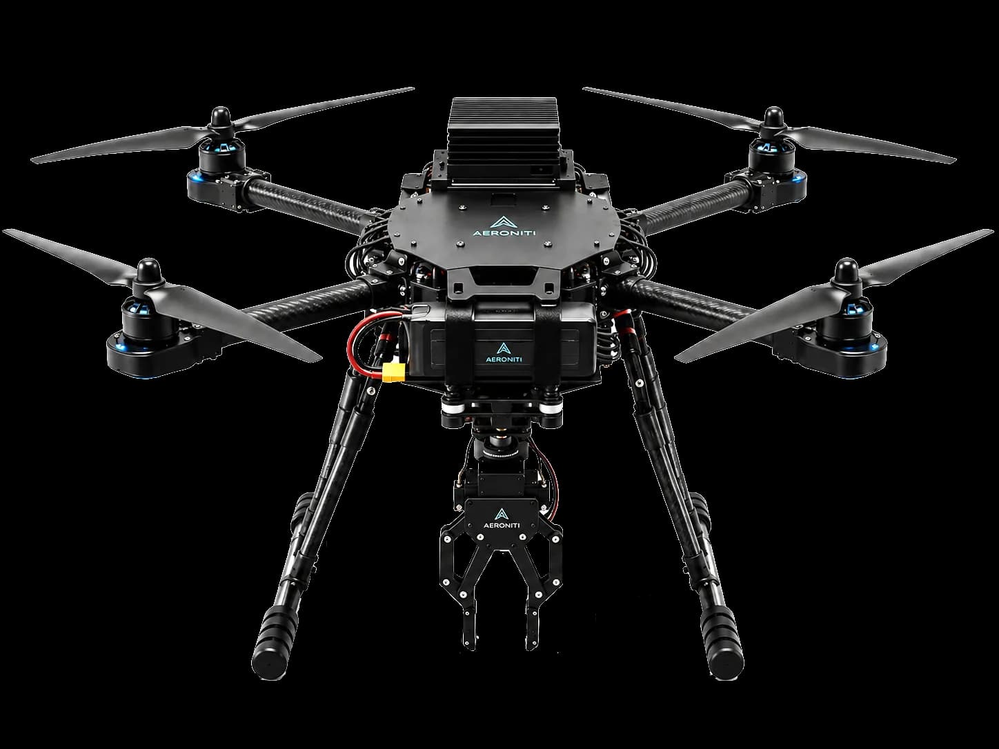
A depth camera estimates distance for many pixels rather than returning only a conventional color image. Depending on the device, depth may come from stereo correspondence, structured light, time of flight, or a combination of methods. On a drone, this can support close-range clearance, object approach, landing cues, dimension estimates, or gripper alignment.
Depth data is not automatically a stable flight measurement. The integration must account for calibration, minimum and maximum range, sunlight, texture, reflective surfaces, motion, vibration, rolling shutter, frame timing, and the transform between camera and aircraft. Decisions should carry uncertainty and expire when data becomes stale.
Architecture flow
The following simplified flow shows where information is interpreted and where flight-safe execution remains separated. Actual interfaces, rates, redundancy, and authority depend on the aircraft and mission.
What depth camera drone means in practice
A depth camera drone uses per-pixel or region-based range information to interpret nearby geometry. The onboard computer converts depth into a useful coordinate frame, identifies a target or surface, estimates relative position, and supplies bounded guidance to a payload or mission controller.
01 — Depth imager
generates depth frames, confidence, and often synchronized RGB data For depth camera drone, verify this against the aircraft, mission objective, compute budget, sensors, communication link, and flight-safety boundary.
02 — Calibration model
describes camera intrinsics, distortion, stereo geometry, and depth scale For depth camera drone, verify this against the aircraft, mission objective, compute budget, sensors, communication link, and flight-safety boundary.
03 — Pose transform
relates camera coordinates to the aircraft, gripper, local navigation, or target frame For depth camera drone, verify this against the aircraft, mission objective, compute budget, sensors, communication link, and flight-safety boundary.
04 — Application logic
turns range and geometry into clearance, approach, alignment, or measurement decisions For depth camera drone, verify this against the aircraft, mission objective, compute budget, sensors, communication link, and flight-safety boundary.
Architecture and component responsibilities
A useful architecture assigns each component a narrow responsibility and makes every authority transition visible. For depth camera drone, system quality depends less on one device than on how data, commands, acknowledgements, and failures move between components.
01 — Frame synchronization
depth, RGB, vehicle attitude, and payload state need compatible timestamps For depth camera drone, verify this against message ownership, update rate, latency, stale-data handling, command acknowledgement, and operator authority.
02 — Data transport
USB or network bandwidth must handle depth, color, confidence, and recording without queue growth For depth camera drone, verify this against message ownership, update rate, latency, stale-data handling, command acknowledgement, and operator authority.
03 — Target coordinates
detection results need a clear frame and covariance or confidence, not an unlabeled XYZ value For depth camera drone, verify this against message ownership, update rate, latency, stale-data handling, command acknowledgement, and operator authority.
04 — Control request
approach and payload motion require rate limits, deadbands, timeouts, and operator override For depth camera drone, verify this against message ownership, update rate, latency, stale-data handling, command acknowledgement, and operator authority.
End-to-end operating workflow
The workflow should describe the system from mission preparation through execution and recovery. The sequence below is deliberately operational: it connects software behavior with checks that an engineering team and an operator can observe.
01 — Calibrate
verify intrinsics, depth scale, mounting transform, focus, and alignment after installation For depth camera drone, verify this against mission state, pre-flight readiness, environmental conditions, flight mode, telemetry freshness, and the defined recovery path.
02 — Filter
remove invalid ranges and unstable edges while preserving obstacles or targets relevant to the task For depth camera drone, verify this against mission state, pre-flight readiness, environmental conditions, flight mode, telemetry freshness, and the defined recovery path.
03 — Measure
select a robust region or three-dimensional model instead of trusting one noisy pixel For depth camera drone, verify this against mission state, pre-flight readiness, environmental conditions, flight mode, telemetry freshness, and the defined recovery path.
04 — Act
approach in bounded stages, remeasure, confirm alignment, and stop when confidence or freshness falls For depth camera drone, verify this against mission state, pre-flight readiness, environmental conditions, flight mode, telemetry freshness, and the defined recovery path.
Engineering design considerations
A technically credible system is built around constraints rather than ideal demonstrations. These considerations shape hardware selection, software boundaries, test coverage, and the conditions under which the capability should or should not be enabled.
01 — Sensor technology
passive stereo needs texture, while active systems may be affected by sunlight or interference For depth camera drone, verify this against power, mass, thermal limits, vibration, electromagnetic compatibility, timing, maintainability, and safe degradation.
02 — Motion effects
vehicle translation, rotation, vibration, and propeller shadow can distort or blur inputs For depth camera drone, verify this against power, mass, thermal limits, vibration, electromagnetic compatibility, timing, maintainability, and safe degradation.
03 — Near-field geometry
landing gear, gripper, payload, and camera placement determine what is visible during approach For depth camera drone, verify this against power, mass, thermal limits, vibration, electromagnetic compatibility, timing, maintainability, and safe degradation.
04 — Closed-loop behavior
measurement noise and latency can create oscillation without filtering, deadbands, and speed limits For depth camera drone, verify this against power, mass, thermal limits, vibration, electromagnetic compatibility, timing, maintainability, and safe degradation.
Limitations and failure modes
No autonomy or sensing capability should be presented as certain in every environment. Identifying limitations early prevents a promising prototype from becoming an unsafe or unreliable field workflow.
01 — Low texture
blank walls or repetitive surfaces can make stereo correspondence unreliable For depth camera drone, verify this against sensor uncertainty, occlusion, weather, range, vehicle dynamics, communications, human factors, and regulatory operating limits.
02 — Reflective and transparent objects
glass, polished metal, water, and dark surfaces can produce invalid depth For depth camera drone, verify this against sensor uncertainty, occlusion, weather, range, vehicle dynamics, communications, human factors, and regulatory operating limits.
03 — Outdoor light
some active depth systems lose range or confidence in strong sunlight For depth camera drone, verify this against sensor uncertainty, occlusion, weather, range, vehicle dynamics, communications, human factors, and regulatory operating limits.
04 — Occlusion
the gripper, payload, aircraft, or target geometry may hide the exact contact region For depth camera drone, verify this against sensor uncertainty, occlusion, weather, range, vehicle dynamics, communications, human factors, and regulatory operating limits.
Verification before flight
Verification should progress from repeatable software tests to integrated hardware and controlled flight. Passing a nominal demonstration is only one result; the team must also test missing, delayed, contradictory, and out-of-range inputs.
01 — Range characterization
compare measured and reference distance across the intended range, target, angle, and lighting For depth camera drone, verify this against acceptance criteria, traceable logs, repeatability, safe abort behavior, manual override, and evidence that each fallback occurs within its allowed time.
02 — Dynamic testing
evaluate error and latency while the sensor and target move relative to each other For depth camera drone, verify this against acceptance criteria, traceable logs, repeatability, safe abort behavior, manual override, and evidence that each fallback occurs within its allowed time.
03 — Calibration checks
confirm transforms after mounting changes, impacts, maintenance, or sensor replacement For depth camera drone, verify this against acceptance criteria, traceable logs, repeatability, safe abort behavior, manual override, and evidence that each fallback occurs within its allowed time.
04 — Controlled interaction
test approach and abort behavior with soft targets and restrained equipment before flight pickup For depth camera drone, verify this against acceptance criteria, traceable logs, repeatability, safe abort behavior, manual override, and evidence that each fallback occurs within its allowed time.
Deployment and operator supervision
Field deployment combines the technical system with procedures, permissions, training, maintenance, and review. Human supervision is most effective when the interface explains what the aircraft is doing, why it is doing it, and which intervention remains available.
01 — Readiness check
verify clean optics, calibration, frame rate, confidence, transform, and target visibility For depth camera drone, verify this against site authorization, checklists, crew roles, data handling, maintenance intervals, incident review, and change control.
02 — Staged approach
reduce speed near the target and require fresh measurements at each interaction phase For depth camera drone, verify this against site authorization, checklists, crew roles, data handling, maintenance intervals, incident review, and change control.
03 — Operator view
display distance, confidence, target position, payload state, and abort control For depth camera drone, verify this against site authorization, checklists, crew roles, data handling, maintenance intervals, incident review, and change control.
04 — Review logs
retain synchronized depth summaries, imagery, aircraft pose, commands, and payload events For depth camera drone, verify this against site authorization, checklists, crew roles, data handling, maintenance intervals, incident review, and change control.
Frequently asked questions
These concise answers summarize common engineering questions. They do not replace the selected hardware documentation, flight testing, operating approval, or a mission-specific safety assessment.
How does a depth camera measure distance?
It estimates range through stereo geometry, projected patterns, time of flight, or another device-specific method.
Can depth cameras work outdoors?
Some can, but usable range and confidence depend strongly on technology, sunlight, surfaces, and weather.
Can one depth pixel guide a gripper?
A robust system uses regions, geometry, filtering, confidence, and repeated measurements rather than one pixel.
Does a depth camera replace LiDAR?
Not necessarily. Each sensor offers different field of view, range, resolution, weight, and environmental behavior.
How often should calibration be checked?
Check after installation and whenever mounts, optics, payload geometry, or sensor hardware change.
Continue with Aeroniti engineering resources
Explore the related product and solution architecture, or bring Aeroniti a specific aircraft, sensor, payload, mission, and operating constraint for a focused technical discussion.